EASIER
If you want a fuel gas conditioning system that’s designed for simple operation and easy maintenance, look no further.
Throughout the project process, you’ll have a single point of contact at Petrogas.
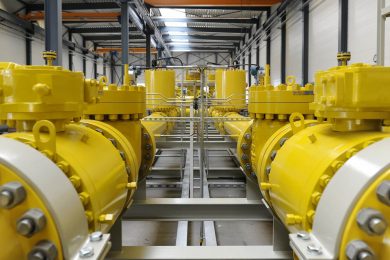
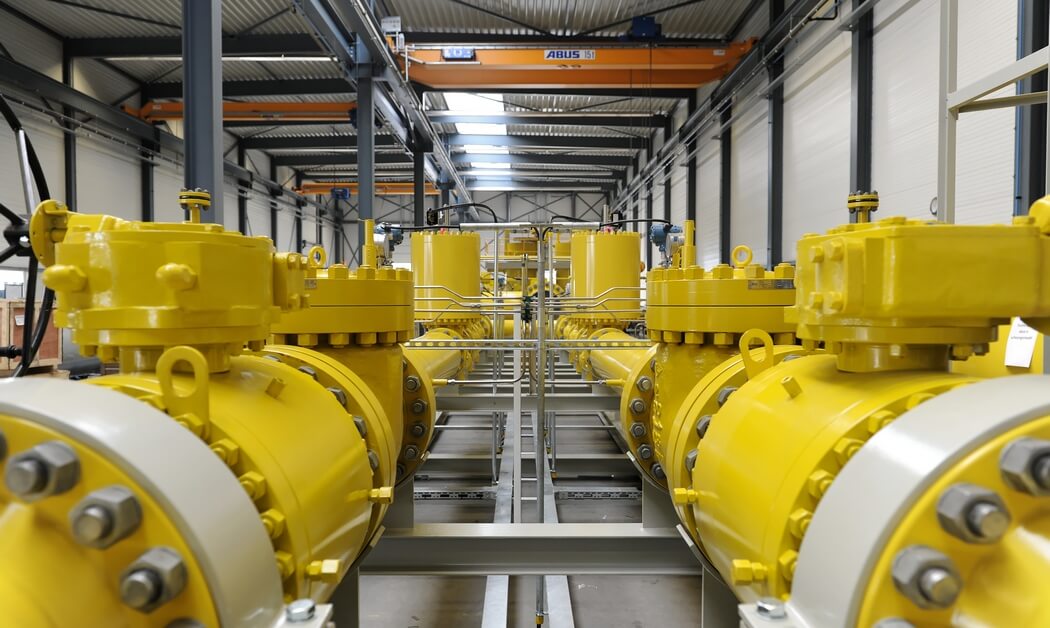
Petrogas fuel gas conditioning stations are produced entirely in-house, with all the gas system sections and engineering work managed by our own skilled engineers. Our engineers keep your maintenance and operation personnel in mind during the design of the system, they ensure that components are easy to reach and maintain.
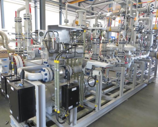
Our modular skid-mounted design shortens commissioning & erection time required on site. We can design and manufacture even the largest gas treatment installations, with capacities of 1 million Nm3/h and above, in modular units.
We offer transparent maintenance contracts to ensure that your system remains in optimum condition. Our in-house service experts are available to provide support during all stages of the systems life-cycle. Our own skilled and passionate engineers can even train your operators on site if required.
Petrogas is a true one-stop-shop for your fuel gas system projects.
SMARTER
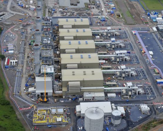
We use state-of-the-art software to define the optimal design for every module in your fuel gas conditioning system. We integrate these modules to form a fully-engineered, tailor-made system that meets all your specifications.
And with decades of experience gained on more than 1800 fuel gas system projects worldwide, we know a thing or two about meeting unique and challenging requirements. Like achieving the optimal system layout for minimal pressure loss – to give you a truly cost-effective solution. Or deploying smart tools for implementing forward-looking preventive and ISA-95 compatible predictive maintenance schedules.
Listening to your requests, we’ve developed gas actuated instruments, which can eliminate the expensive auxiliary systems that are sometimes needed. We constantly make our systems smarter by using the market’s most advanced measurement components and integrating them with our own control systems (again compatible with ISA 95) and custom made software. That gives the most accurate measurements possible to ensure your operation and maintenance personnel have the right information to base their decisions on.
Lean management techniques and long-term supply partners shorten our delivery times of fuel gas systems, components and spare parts.
BETTER
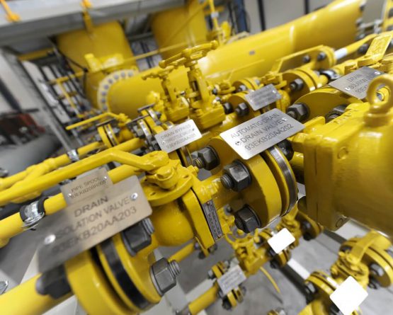
Wherever you are in the world, all the electrical and mechanical components of our fuel gas conditioning systems are designed and built to suit local conditions, regulations and standards. We offer full redundancy of critical components, to ensure minimum downtime and continuous operation.
Using state of the art engineering software, we fine-tune your gas conditioning system design and layout to reach maximum efficiency, reliability, and performance.
We build all fuel gas treatment systems to the highest standards. We ensure that all relevant national and international regulations for supply quality, health, safety and the environment are followed to the letter.
Lean manufacturing techniques minimize waste and reduce lead times. State of the art components and systems are customized to your exact needs … and built to confirm to even the strictest standards.
Petrogas can advise on gas treatment solutions for extreme environments: we have delivered fuel gas installations suitable for the most hostile environments, from Siberia to the Sahara. We design your gas conditioning system to ensure a long life and reliable operation in the harshest environments.
Crucially, in areas with security risks, we always work with qualified local personnel.
System sections
The safe choice in inlet valves for fuel gas conditioning systems
The inlet valve is a crucial section in any fuel gas conditioning system; it will seal off the fuel gas system from the fuel gas supply line to safeguard the entire downstream plant in case of an emergency. The fuel gas inlet shuts off the fuel gas supply automatically on a downstream alert using a Emergency Shut-Down (ESD) Valve or Safety Shut-Off Valve (SSOV).
The fuel gas inlet section can be opened or closed from a central control room, or locally at the ESD valve itself. The gas inlet section easily adapts to single line (1×100% flow), dual line (2×100% flow), or other fuel gas inlet design configurations.
Pressures are equalized upstream and downstream of the ESD valve, to prevent the Emergency Shut Down valve seals from excessive wear.
- We use state of the art components to guarantee plant safety at all times. The main inlet valve allows pigs to pass through, and has various options including different makes and types of fail-safe actuators:
Electric with fail-safe controls
Pneumatic (operated by instrument air or instrument gas which is conditioned at a take-off point downstream of the valve)
Gas-over-oil to allow reliable operation on sour and wet power gas
Separation removes large quantities of contaminants from the gas flow
To remove large quantities of contaminants from the fuel gas stream a knock-out drum (KO drum) can be installed upstream of the filter separator in the fuel gas conditioning system. The knock-out section removes the majority of debris and liquids in the fuel gas stream. Additionally, the KO drum prevents premature saturation in the downstream filter elements installed in the filter vessel and protects the fuel gas filters from liquid slugging. The knock-out vessel internals slows down the gas velocity and allow gravity to pull the fuel gas contaminants down in the vessel where they can be removed.
- Options include:
ASME U-stamp / AD2000 / PED vessel certification
Demister package for aerosols removal, removable through man hole
Vertical or horizontal orientation
"Drip-barrel" technique
Integrated level control instrumentation - Float, guided wave radar, vibrating fork type switch
Gas filtration keeps downstream equipment safe from foreign particles.
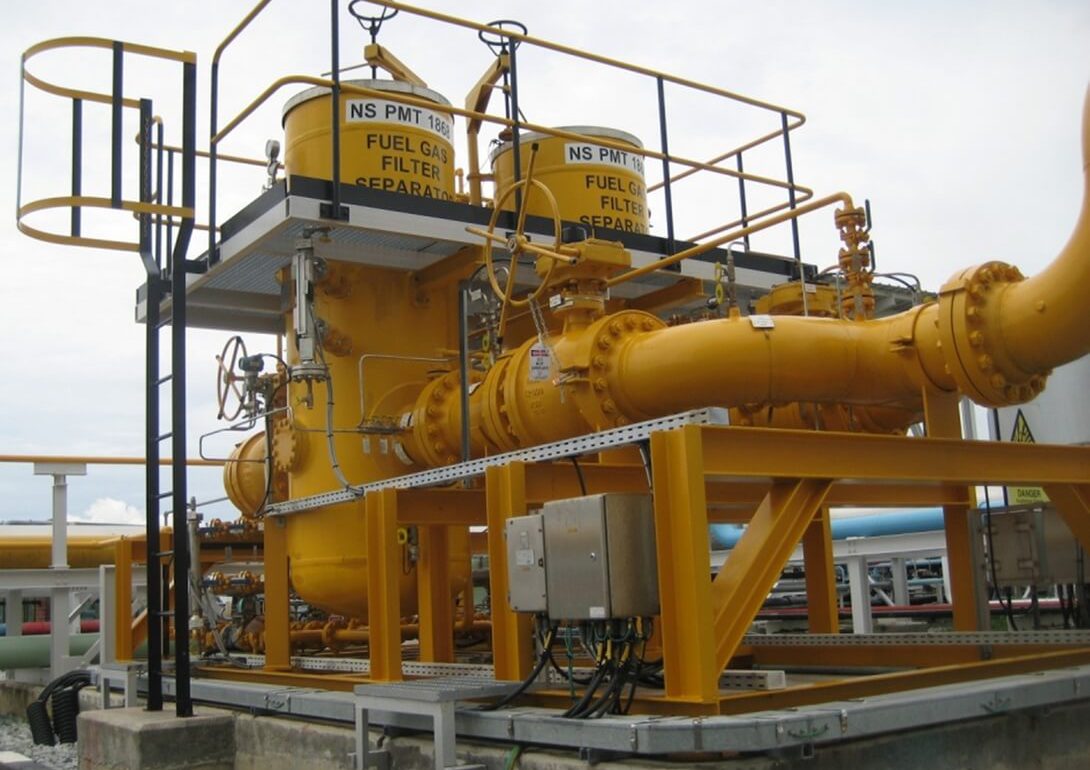
The fuel gas filter separator removes foreign materials like debris, dust and liquids to prevent them from damaging downstream systems. We monitor any rising differential pressure between inlet- and outlet of the vessel, which indicates that the filter elements should be replaced.
We have worked with gas supplies having high acid and salt content, always conditioning the gas to give a clean dry stream to turbines for maximum up-time. Filters are automatically or manually drained, and there are various mounting orientations for easy operation.
- Options include:
ASME U-stamp / AD2000 / PED vessel certification
Baffle plate, Mono- or Multi Cyclone primary separation stage
Liquid, Dust or Coalescer filter cartridges in secondary filtration stage
Bolted top cover or quick closure for easy access to filter cartridges
Self- or manually draining
Single-, double- or triple-redundant control
Parallel runs: eliminate downtime, automatic run switching is possible
Horizontal or vertical vessel orientation
Easy condensate storage for fuel gas conditioning systems
The fuel gas condensate storage section holds drained material from the filter separator (and/or Knock-out drum) until it can be hauled from site. As elsewhere in our system, we use proven and reliable technology and can customize the design to your exact requirements.
The vessel can have an unlimited range of volumes, depending on your specific needs.
Options include single-wall tank or double wall for additional containment safety, a vacuum leak detector, condensate unloading pump, various level measurements, and a flame arrestor for maximum safety.
A knock-out drum with optional demister can be installed where the natural gas is accompanied by considerable quantities of water, hydrocarbon condensates or other fuels. Here, too, condensates can be drained manually or automatically to a storage facility.
Real-time monitoring of liquid level with level indicator signal sent to control room. There’s a manhole for easy access.
Options include single-wall tank or double wall for additional containment safety, a vacuum leak detector, condensate unloading pump, various level measurements, and a flame arrestor for maximum safety.
Accurate metrology for fuel gas conditioning systems
Fuel gas flow meters let you keep a close eye on the precise amount of fuel gas being consumed. Volumetric or mass-flow meters monitor fuel gas volumes for custody transfer (Sm3/Nm3, energy value in megajoules), gas turbine efficiency monitoring and quality control.
Fuel gas flow meter sections can measure flows of 1 million Nm3/h and above with accuracies to within 0.1%. Automatic reporting (hourly, daily, weekly) can include pressure, temperature, and energy value per standard cubic meter for billing.
A flow computer can compensate measurements for fuel gas temperatures and pressures, and a gas analyzer calculate the correct energy intake. Petrogas offers various advanced measuring methods and fuel gas metering system layouts for easy operation and maintenance.
- Options include:
Various types of meters; Turbine, Rotor, Ultrasonic, Orifice, Coriolis, etc
High pressure actual gas medium calibration
Single or redundant metrology and control
Parallel runs eliminate downtime
Calibrated at operating pressure before delivery
Approved to all relevant industry standards
Accurate analysis for fuel gas conditioning systems
The analyzer section can report the composition of gas components and calculate or measure the heat value, dew point and other values. These values need to be measured and reported accurately for custody transfer payments or for gas turbine burner control.
The sample probe guides a small stream of reduced -pressure gas to the analyzer, which cracks the gas into multiple components and vents waste gas to a safe location.
- Options include:
Gas chromatograph
Wobbe-analyzer
(Total) sulphur analyzer
Dew point analyzer
Any combination of the above
Boosting pressure in fuel gas conditioning systems
Where needed due to low inlet pressures from the gas supplier, pressure boosting compressors increase the pressure to gas turbine levels and can be installed in parallel with the heating and pressure-reduction sections. The pressure booster is integrated in our control narratives in close cooperation with well-known compressor suppliers and uses proven technology.
Operation and maintenance is easy
Maintenance schedules can use live operational data
Options include a turbine compressor for boosting pressure
Versatile heating for fuel gas conditioning systems
The gas temperature drops significantly when pressure is reduced for gas turbine consumption. This Joule-Thomson-effect is countered by heating up the gas prior to pressure let-down, and prevents liquid dropout from the gas if one of the components passes below its dew point. strategically located sensors and switches monitor the design temperature, water level and pressure, safeguarding the entire system.
Any additional results of a risk assessment/hazard and operability study (Hazop) can be implemented in the control philosophy for each project section.
- There’s a choice of heating methods:
Gas fired indirect Water Bath Heater:
- pressurized
- atmospheric
- nitrogen blanketed
- with retractable fire bundle (as per API 12K)
- water or oil for heat transfer medium
- with an internal bypass valve that allows very responsive gas temperature controlGas fired Boiler + shell&tube heat exchanger
Electrical heater
Package can be supplied in a custom built vented container, free standing under a shelter or located in an adjacent building
Reducing pressure in fuel gas conditioning systems
This section reduces the gas pressure to a stable level suitable for gas turbines, with the actual pressure being determined by self acting regulator valves. Remote set-point adjustment can fine tune the output pressure for each individual run, or force run switching for even wear on parts.
Pressure reducing components vary depending on pressure levels, pressure differences, and allowable pressure drop across the system for low inlet pressures.
- We work closely with regulator valve manufacturers to ensure the best solution for every situation:
Fluctuations in inlet pressure are smoothened out to ensure a stable gas feed to the turbine
Custom sizing software ensures ideal valve and pipe sizing
For highest safety, every reduction line has one or two safety devices depending on local regulations and industry standards
Reliable buffering as part of the fuel gas conditioning systems
The fuel gas buffer system consists of a high pressure compressor, a buffer volume and an integrated outlet system (usually a heater and pressure reducing system). The goal is to store enough fuel gas to keep the gas turbine running in case of a interruption in the fuel gas supply . The fuel gas buffer must provide enough gas to the turbine to overcome the time required for the turbine control system to respond; like switching over to backup fuel (usually fuel oil diesel), start pumps and adjust burner settings.
The fuel gas buffer volume is optimally sized for each project, since each combination of gas pressure, composition and the site specific turbine’s consumption requires a different fuel gas buffer volume to bridge the time required to perform a switch-over to an alternative fuel.
The compressor feeds gas into the buffer volume at a high pressure (80-100 barg). If the inlet pressure drops and the online pressure reducing system fails to supply enough pressure, the buffer reducing valves automatically supply the gas and signalling the main control system the fuel switch-over is to be initiated.
Ideal type and make of compressor are specified for each project (Petrogas works brand independant)
Oil-free compressors prevent fuel contamination
There are multiple cooling options
The buffer volume is not only sized per project, available plot size is also factored in. Vertical gas vessels or stacked piping is an option to save space
Safe venting, flaring or incineration for fuel gas conditioning systems
Every fuel gas vent or safety valve outlet can be routed to a central point and be either vented to a safe location or burned. In case of an over-pressure situation or a system purge prior to maintenance, all combustible gasses are disposed of safely. Operation is automatic, and maintenance is simple. Our systems are designed with state of the art software by our in-house EX specialists to ensure inherent safety.
Flaring reduces greenhouse gas emissions. We can help you reduce emissions further using an incinerator to burn the waste gas, condensate and other pollutants at extremely high temperatures.
Reliable, proven technology helps assure high quality and safety
Options include cold-vent, flare stack, or incinerator
Final run components for fuel gas conditioning systems
The final run of the fuel gas treatment system is formed by an integrated series of equipment that form the last line of defense to protect the Gas Turbine from foreign material. The final run components may include fuel gas consumption flow metering, performance heating, filtering and a shutoff valve section.
Control system for processing equipment
The control system consists of components such as a Programmable Logic Controller (PLC), Input/Output cards, barriers, flow computers, relays, motor soft starters and UPS. These can be housed in a custom build air-conditioned control container, with dimensions varying according to customer specifications and requirement.
Operators gain complete insight in the fuel gas systems real-time performance with precise control across the full range of operating pressures and temperatures. When needed, the Petrogas after sales service team is available to provide remote service assistance and diagnostics across the web.
The control panel can be operated locally, or remotely from another site. Petrogas can supply data communications to the main plant control room.
Case studies
Short 32-week turnaround time
Fuel gas inlet station for power plants
- What did our customer request?
-
This project was part of an agreement between Siemens and the Egyptian government to add 50% more energy to the power grid within a number of years. We were asked to supply the Fuel Gas Conditioning Station for three of the prospective power plants (Beni Suef, Burullus and New Capital). After completion in May 2018, the three power stations will be the largest gas-fired, combined cycle power plants ever built and operated in the world. And they will supply enough electricity for 45 million people.
- Our solution
-
Petrogas delivered the fuel gas systems for the 24 H-Class gas turbines, designing, engineering and fabricating the system sections. In particular, we developed a custom DRIP-barrel (horizontal liquid separator) and also supplied Emergency Shut-Down, inlet filters, electrical heaters and control cabinets.
- What set the project apart?
-
We usually build all the pressure vessels and pipes in our own workshop in Eindhoven, the Netherlands. Because of the size of the project, though, we outsourced part of the production to some of our expert subcontractors.
Together, we helped Siemens to set a new worldwide benchmark for the execution of a fast-track power generation project. After completion of the first phase Siemens was already able to connect 10% more power to the grid than forecast, a surplus sufficient to supply electricity to an additional one million people in Egypt.
- What were the project challenges?
-
“The short turnaround time was a real challenge. For a project like this it is usually 10 to 12 months, but we delivered the installation within 8 months. Siemens was delighted with the result and the plants actually achieved first-fire well ahead of schedule.”
- What did our customer request?
-
Cegelec needed more electric capacity at a petrochemical industrial complex on Das Island off the coast of Abu Dhabi. Petrogas was asked to supply the fuel gas conditioning units for the natural gas powered turbine generators. These units ensure that the gas arrives at the gas turbines under the right conditions.
- Our solution
-
The natural gas was being sourced from different locations, so there were differences in pressure, composition and temperature. Gas from one of the suppliers also had high acidity. Petrogas supplied the installation to filter and heat the gas and reduce the pressure.
- What set the project apart?
-
The limited amount of space on the island meant the installation had to be as compact as possible, while leaving enough room for operation and maintenance.
- What were the project challenges?
-
“Initially, the requirements for the fuel gas conditioning units were fairly basic. But as the project progressed, several new key design requirements became evident. We pride ourselves on our versatility, and responded quickly to incorporate all the additional demands.”
Dedication and hard work
Ras Al-Khair Power Plant (fuel gas system)
- What did our customer request?
-
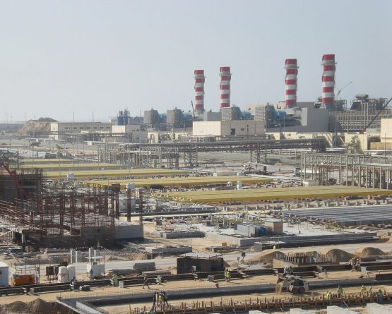
The Saline Water Conversion Corporation is a Saudi Government Corporation responsible for producing electric power and desalinating seawater. The SWCC Ras Al Khair project was at the time the largest combined power and desalination plant in the world and won the prestigious “Desalination plant of the year” award in 2015. It is a landmark project for SWCC.
The plant converts more than 1 billion litres of seawater into potable water each day, transforming the potable water situation in Riyadh, one of the world’s fastest growing and most water-stressed cities. The plant also produces 2400 MWe of electricity for the Eastern Province of Saudi Arabia and helps to power the nearby Ma’aden/Alcoa Aluminium plant.
The power plant is gas & oil fired, and Petrogas won the contract for the fuel gas conditioning station with 1 million Nm3/h capacity for 12 gas turbines, along with the backup fuel oil system to ensure a high quality, reliable and continuous supply of fuel for the turbines. Waste heat and reverse osmosis are used to desalinate 1 billion litres of sea water per day. - Our solution
-
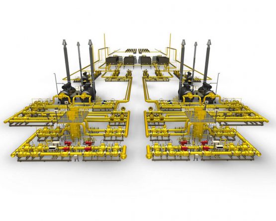
In close cooperation with the owners’ engineer Pöyry, we designed six identical blocks. Each had two mirrored gas conditioning systems including Emergency Shut-Down valves, filters, flow meters, heaters, pressure reducing systems for GTs and boilers, pressure boosting compressors and a high pressure gas buffer system. Petrogas built the skid-based system in workshops in the Netherlands and China, and erected and commissioned the system on site.
- What set the project apart?
-
Because Petrogas has both engineering and fabrication in-house, our customer benefitted from our practical experience in the initial basic design phase. The design was optimized before Petrogas built the skids, wrote the control software and performed the on-site commissioning.
The system can boost gas pressure for a prolonged period and can maintain gas supply for several minutes when the gas feed is interrupted to allow the turbines to switch to fuel oil. Petrogas played a substantial role in drawing up the operating philosophy between all these systems. - What were the project challenges?
-
“The sheer size of the project made it a challenge. The system is actually twelve complete 12” gas conditioning systems with 100% redundancy. The photo shows the stacks of the Water Bath Heaters, 36 in total.
Resources, planning, logistics between several workshops and dozens of suppliers all required a creative approach. The order came in 2011 when we already had a healthy backlog, and the order was worth about a year’s turnover. Petrogas successfully completed the job thanks to the dedication and hard work of our personnel and suppliers. “
- What did our customer request?
-
Our customer required a fuel gas conditioning station for the Al Diwaniya project. The station prepares and conditions the gas before it enters the turbine, ultimately to generate electricity. The conditioning entails filtering, heating and reducing the pressure.
- Our solution
-
Petrogas supplied the Fuel Gas Conditioning Station, including hardware and control systems. A fuel gas metering system measures the gas used, and a safety valve shuts down the gas supply in case of extreme pressures or temperatures.
- What set the project apart?
-
Petrogas also performed part of the overall engineering. From our experience in similar projects, we advised the customer to approach a number of things differently to improve safety and efficiency.
- What were the project challenges?
-
“Al Diwaniya is located around 250 km south of Baghdad, in a region with security risks. Thanks to our local network of qualified professionals we assembled and commissioned the system on site. An innovative design meant we could easily mount the skids against each other on site, leaving just the bolts and nuts to be tightened.”
Contact us
Would you like to discuss your fuel gas conditioning project with our Experts? Please feel free to contact us.
Direct contact with our Experts
Your interest
Fuel Gas Conditioning
