EASIER
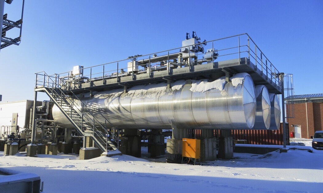
When you want a reliable processing system that’s designed for simple operation and easy maintenance, you have found it. During the complete life cycle of the Glycol Dehydration & Regeneration system, our passionate engineers will provide professional support when you need it.
During the systems development phase we work in close cooperation with our valued clients to fine-tune the systems design to your specifications.
Petrogas dehydration systems are produced entirely in-house, from the first design and engineering work al the way up to the tightening the final bolt prior to start-up, commisioning and after sales , the entire project is managed by our own skilled engineers, a true one stop shop.
The Petrogas project manager will be entrusted with the stewardship of the project. Throughout the project process, he will be your single point of contact from project kick-off up to the commissioning on site.
Lean management techniques and the efficiency of our long-term supply partners shorten your delivery times.
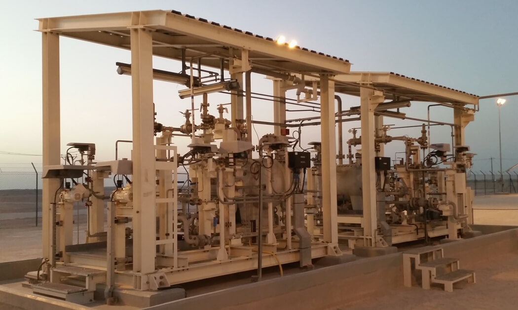
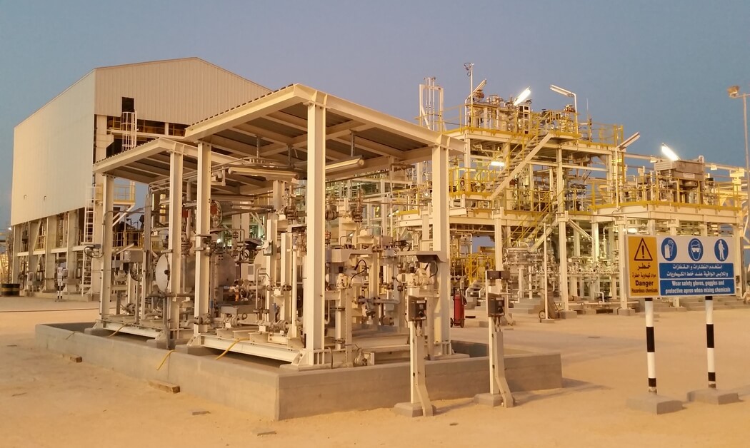
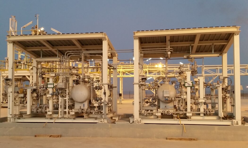
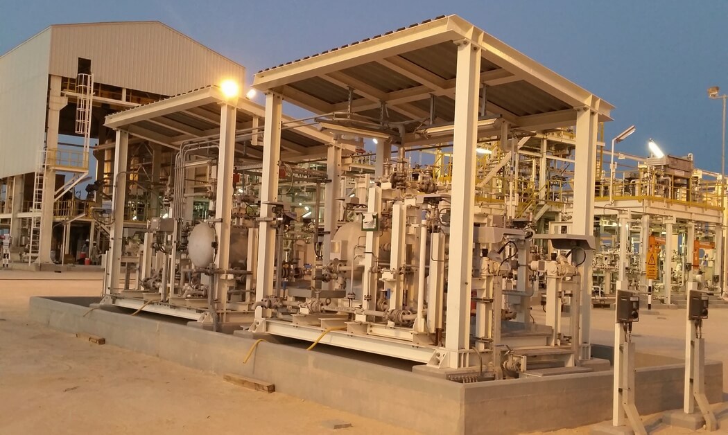
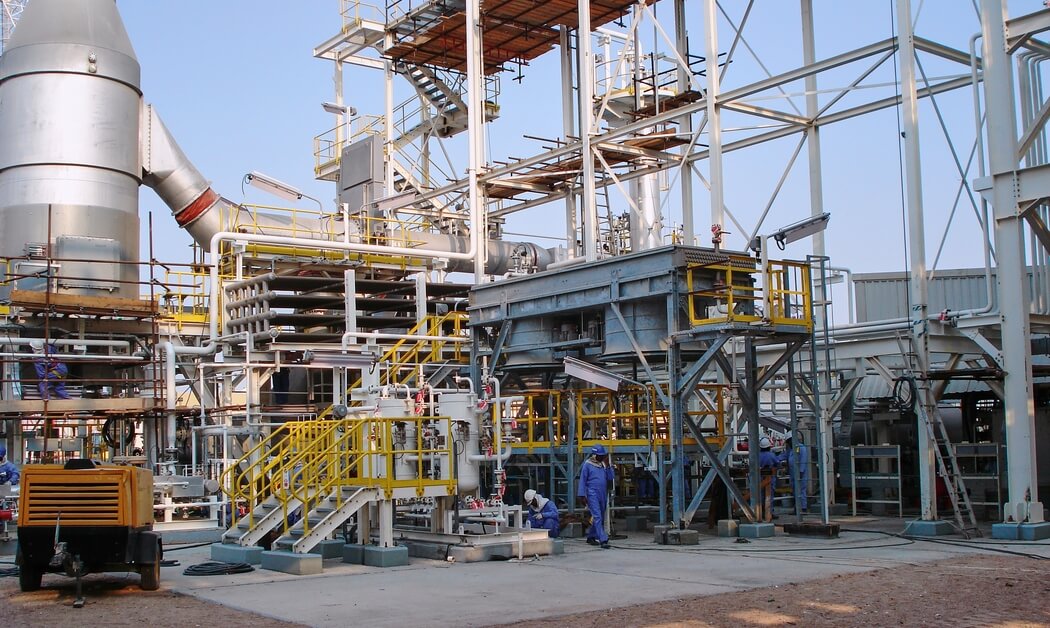
Our modular skid-mounted design shortens erection & commissioning time on site according to the turnkey concept.
Our after-sales services are managed in-house, and made available through a range of transparent maintenance contracts – including Petrogas supervision on contracted maintenance projects. Preventive maintenance contracts ensure the highest possible system availability and uptime, freeing you from any concerns about maintenance status. There’s a service hotline, and the specialist help minimizes risks. As a final touch we can offer remote support if you need it.
SMARTER
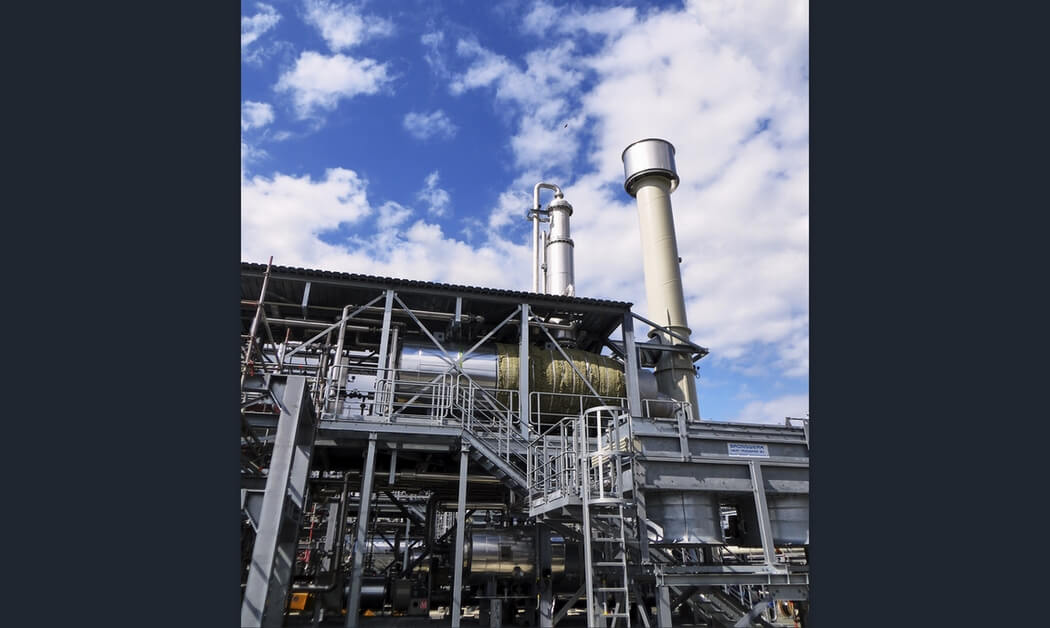
To stay at the forefront of technology we continually develop and innovate the Glycol Dehydration & Regeneration systems. Our passionate engineers integrate the latest practices in our designs.
We support our clients with advanced data acquisition and management to obtain detailed insight in the systems real-time performance. We analyze this data together with our clients to further optimize absorption cycles.
Our aim is to provide operators with the facts they need to fine-tune and optimize the system to the plant it’s operational situation. We constantly make our systems smarter by using the market’s most advanced measurement components and integrating them with our own control systems (compatible with ISA 95 standards). Our custom made software provides accurate real-time measurements and information straight to the control centre, so that your operation and maintenance personnel have the most up-to-date information available to base their decisions on, right at their fingertips.
BETTER
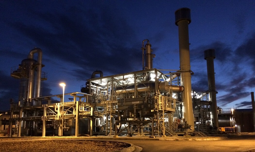
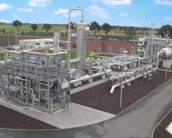
Petrogas Glycol Dehydration & Regeneration are designed and built to suit local conditions and regulations. The design is optimized to reach maximum efficiency for the situation and parameters at your specific site.
We built according to the highest standard. State of the art components and systems are customized to your exact needs. At the hand of the project specific design we will start with the component selection procedure. Each component is selected based upon extensive research. We look beyond obvious factors such as; fit for purpose, quality, lead time and cost, we look at: safety, energy efficiency, technological alternatives and the availability and exchangeability of spare sparts.
With our state of the art operating system you will be able to continuously monitor the performance in real time.
All factors are considered to ensure that we can guarantee your system is future proof and will be able to run on maximum efficiency during its operational lifetime.
System sections
Removing free liquids and collection from the feed gas
The Inlet Separator scrubs the feed gas from free liquids, like (salty) water and hydrocarbon condensate, and suspended particles before it enters the Absorber. In case large amounts of water, condensate are expected this can be collected in the Inlet Separator also. Not removing these liquids from the feed gas may result in higher glycol losses, increase foaming and increase the Reboiler duty. The Inlet Separator can be stand alone or an integral part of the Absorber.
Internals selection and liquid hold-up volume optimized for the application
Removing dissolved liquids from the feed gas
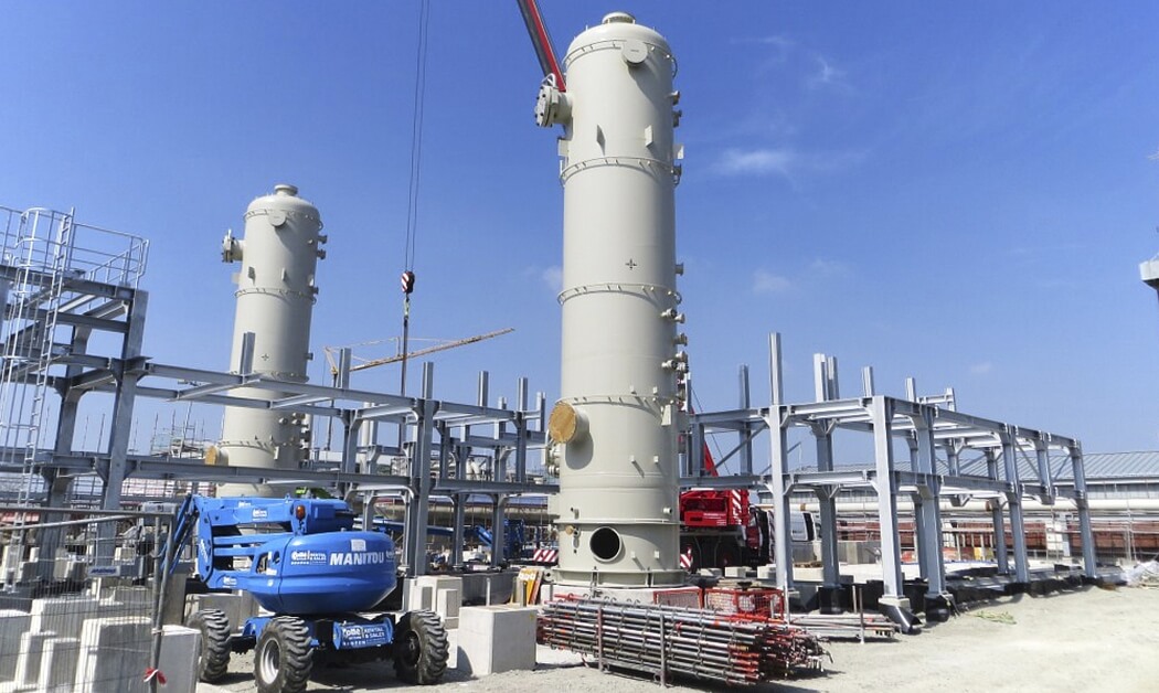
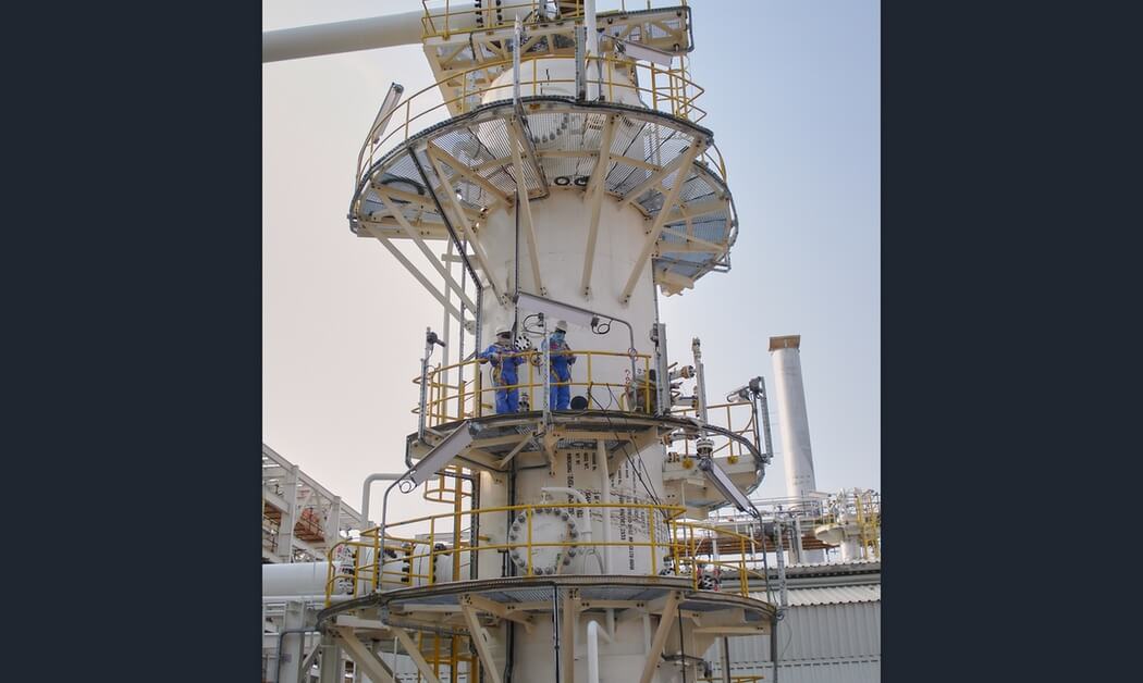
The Absorber removes dissolved liquids, like water, hydrocarbon condensate, aromatic hydrocarbon contaminants and BTEX. TEG flows generally from top to bottom in countercurrent with the saturated feed gas. The contacting devices may be packings or trays in combination with several types of internals. Water rich glycol leaves the Absorber at the bottom of the vessel. The dry gas leaves the Absorber at the top via a demisting device to remove entrained droplets.
Inlet Separator may be included in the Absorber vessel
Optimum selection of internals for absorption, dispersion, collection and hold-up
Removes gaseous hydrocarbons and separates liquid hydrocarbons and glycol
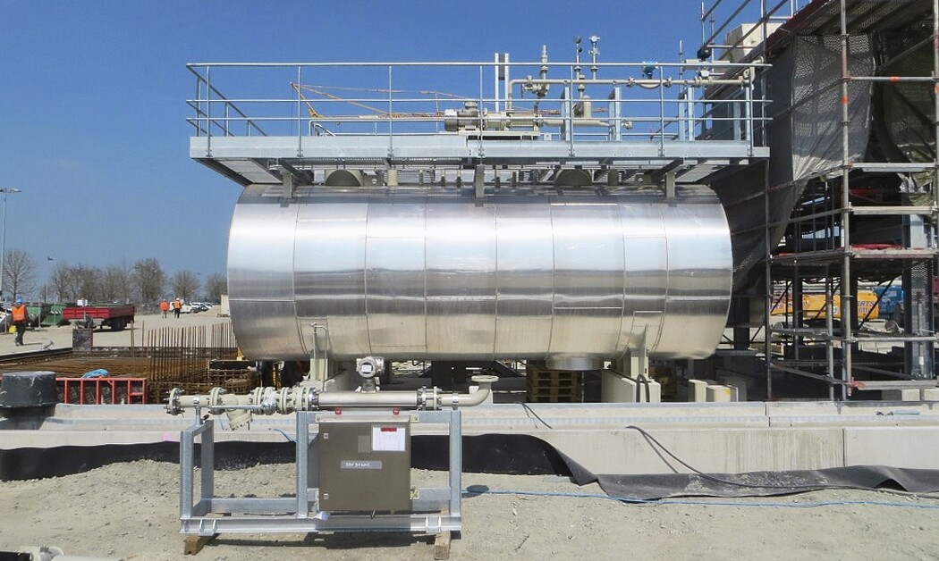
In the Flash Vessel the pressure is reduced which enables flashing of dissolved gaseous hydrocarbons including Sulphur gasses and carbon dioxide. To improve the degassing the rich glycol is generally preheated in the Reflux Condensor. The rich glycol remains in the Flash Vessel for a certain period to enable separation of liquid hydrocarbon and glycol based on the difference in gravity between the two media.
Internals selection and liquid hold-up volume optimized for the application
May serve as collection vessel between the dehydration sections and glycol regenerators
Removes solids to protect downstream equipment
The Glycol Filter removes solids from the glycol which might collect in the regeneration system. To increase operational uptime glycol filters might be redundant. The differential pressure between the inlet and outlet is monitored to indicated fouling of the filter element.
Removes organic hydrocarbon compounds
The activated carbon absorbs troublesome organic impurities from the glycol to reduce foam formation. The activated carbon filter should be installed downstream the glycol filter to prevent collection of debris in the activated carbon filter. This can be well treating chemicals, compressor oils or BTEX components. Fouling of the active carbon is based on absorption so the only way to detect the carbon is no longer active is to check that the glycol is still clear.
Heat recovery from regeneration section
After leaving the glycol regenerator the lean glycol has to be cooled down to approximately the feed gas temperature. A part of this heat is used to heat the rich glycol before feeding it to the still column of the regeneration section. It reduces the duty of the reboiler and maximizes the use of thermal energy which would otherwise by expended. The glycol heat exchanged is generally a shell and tube heat exchanger.
Regenerates glycol far above 99.5% purity
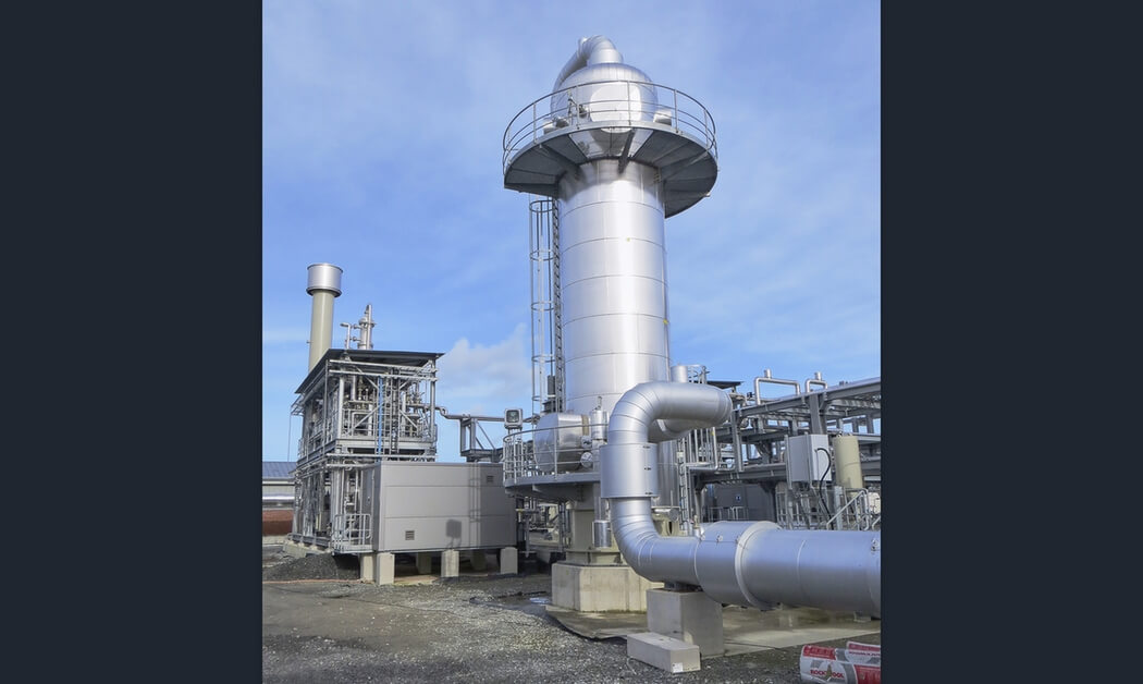
The glycol regenerator or still column includes several sections. The reboiler heats the glycol to approximately 200°C. The glycol regenerator is a packed column mounted on top of the reboiler vessel. Flashed rich glycol is feed in the middle of the packed column. The rich glycol is brought into contact with the hot vapors from the reboiler and is stripped before entering the reboiler vessel. The top of the packing is a reflux section to recover glycol from the vapor. Water vapor leaves the still column at the top. A regenerator condenser may be installed at the top of the glycol regenerator to preheat the rich glycol to enhance flashing and to cool down the water vapor before it leaves the regenerator. Lean glycol leaves the reboiler vessel.
The reboiler can be heated by means of an electrical heater, hot oil/ steam or direct gas fired. In the latter case flash gas, in case suitable, can be used as fuel gas for the reboiler burner. For a more compact design the stripping column might be integrated in the reboiler vessel thus also serving as weir to ensure the heating coils are always submerged in liquid.For the packed columns trays, structured packings or random packings may be used. A random packing generally serves the purpose and is recommended from a sizing and cost point of view.
Enhances glycol purity up to 99.9%
The stripping column is a packed column where dry natural gas is brought in intimate contact with the lean glycol and strips the lean glycol from the remaining water.
Glycol buffer
The surge vessel is a buffer vessel between the glycol regeneration section and the dehydration section. Depending on the application the size and location of the surge vessel are determined. If required glycol is added to surge vessel to compensate for the glycol losses during the dehydration and regeneration process.
Booster Pumps
The glycol circulation pumps is the driving force to transport the lean glycol from to the absorber at the correct pressure.
Booster pumps can be installed to facilitate transportation of glycol between e.g. between the flash vessel or surge vessel and the glycol regeneration section. These are typically centrifugal pumps. Redundant execution is typically used to increase operational availability of the system.
Cools lean glycol to just above the feed gas temperature
After being cooled down in the glycol heat exchanger the lean glycol needs to be cooled down to approximately the feed gas temperature before entering the absorber. Depending on the application and client wishes the cooler can use several coolants like e.g. air, water or the gas leaving the contactor. However air coolers are most commonly used.
Control System
The control system consists of elements like Programmable Logic Controller, Input/Output cards, barriers, flow computers, relays, motor soft starters and UPS. These can be housed in a special conditioned container, with dimensions varying according to customer specifications.
Operators miss nothing with precise control across the full range of operating pressures and temperatures. When they need it, there’s remote assistance and diagnostics across the web.
The control panel can be operated locally, or remotely from another site. Petrogas can supply data communications to the main plant control room.
Case studies
Responding quickly
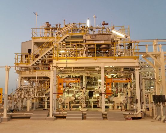
Al Noor glycol regeneration unit
- What did our customer request?
-
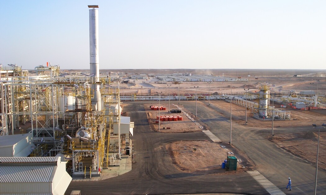
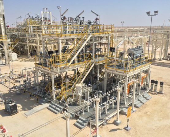
The Al Noor oil production site in Oman also yields a lot of natural gas. It is injected into a well using high-pressure compressors. This technique also required installing a natural gas drying installation using tri-ethylene glycol as drying agent.
- Our solution
-
Petrogas supplied a contactor column where natural gas is exposed to tri-ethylene glycol under high pressure. The glycol adheres to the water and is then separated from the gas. The glycol regeneration unit then removes the water from the glycol and ensures the glycol can be recycled continuously: the saturated glycol is collected in a waste trap and depressurised to release various contaminants. The glycol is then heated to 190ºC to boil off the heavier hydrocarbons.
- What set the project apart?
-
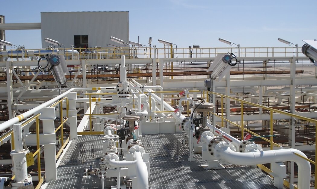
The Al Noor natural gas has extremely high acidity. That risks corroding the pipes, and the customer therefore specified high quality materials. In the end we selected Incoloy and Hastelloy for the job.
- What were the project challenges?
-
“During the engineering phase we discovered that the natural gas also contained significant amounts of salt. Salt has an adverse influence on glycol, and can accumulate in the system. We therefore had to reconsider the project design. Within a week we had put together a multi-disciplinary team to deal with the new situation, and presented a viable and cost effective solution to the client.”

Contact us
Would you like to discuss your project with our Experts? Please feel free to contact us.
Direct contact with our Experts
Your interest
Glycol Dehydration & Regeneration
